Do you want to design a completely new linkage? Or modify or optimize an existing one? With the kinematics software ASOM you can now also use parametric constraints to describe your kinematic system even more conveniently.
Function selection
Save time and nerves when dealing with complex problems
Engineers are well aware of this fact: kinematic problems can be very time-consuming. The slightest changes can quickly cause your entire concept to spiral out of control. If forces, mounting zones, and other restrictions also have to be taken into account, it can often take months to find a viable solution. ASOM, on the other hand, has adopted the strategy of automatically maintaining various partial aspects of a solution in order to reduce the complexity of the problem as much as possible for you.
Additionally, you can use parametric constraints in ASOM to define the initial state of your simulation or to influence it constructively only in a very specific intended way when making adjustments.
Let our syntheses assist you
ASOM offers various tools that can automatically maintain partial aspects of a solution. On one hand, there exist various geometric syntheses to assist the user in creating linkages that automatically fulfill certain transport conditions (plane on plane or point on point).
In addition, there are other tools, such as the holding load synthesis, which can be used to specify and fix certain desired forces or torques, and the energy storage synthesis, which can automatically fulfill certain requirements regarding the lengths of energy storages (e.g. a gas spring being always fully extended at the end of the movement, the possibility to also edit energy storages in their end position).
Visual results in real time – or even faster
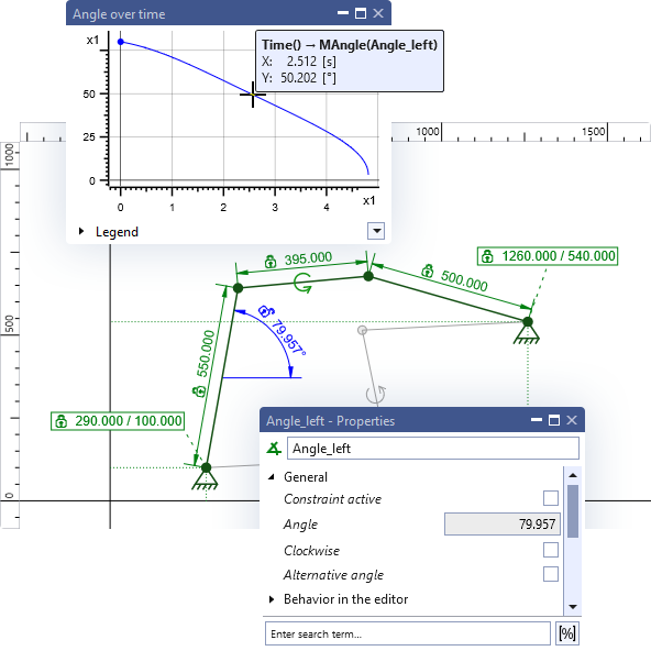
See how your measured parameters, your secondary conditions, your diagrams, and any previews for your system's final state or intermediate positions respond to your inputs in real time. The effect of every change you make is simulated and visualized in real time. This makes the development process immediately tangible and intuitively understandable, and allows you to quickly test out entire parameter ranges or mounting zones.
Use our wide range of display types to keep an eye on all the information you need about your system at all times. Understand quickly and interactively what possibilities your system has – or does not have – and act accordingly.
Display types: you decide what you want to see
In order to always be able to display data exactly as you wish, ASOM provides various display types: graphs/diagrams (graphical displays), expressions (numerical/textual displays) and visualizers (graphical displays directly on the canvas). Parametric constraints can also be used to display their parameter values while playing back simulations.
The visualizers include trajectories of points, display of the instantaneous center of rotation, but also previews of ending or intermediate positions of your system via element shadows, as well as the display of joint or bearing forces as vectors, and much more.
Extensive import and export capabilities
In ASOM, you can import both DXF files and images (BMP, JPG, PNG, etc.) to integrate sketches of your components into the simulation. This allows you to easily take mounting zones and other details about the environment into account in your model.
In addition, things like polygons and spline rails can also be exported individually and imported again, e.g. to reuse them in a new project. Likewise, you can export any diagram data, as well as the complete geometry of a project as DXF, e.g. to evaluate it externally or to transfer it to CAD applications. Expressions can also be used to export data in a targeted and structured way.
Do you already know our training courses?
We offer different training options, both on site and online, so that you can use the full range of functions of our kinematics software ASOM.
Create realistic presentations quickly and intuitively
Attach imported sketches, images, or simpler graphical elements (polygons, rectangles, etc.) to moving components to give them more realistic shapes. Change the colors of various elements on the canvas to highlight them or make them more visible.
Use the various playback options for simulations in ASOM to especially easily create closed motion cycles, e.g. for presentation, or change the camera position to make relative movements of parts more visible. This will allow you to quickly get a detail-rich simulation that you can use to present your solution.
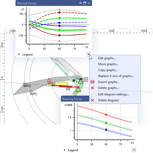
Calculate forces any way you want – even parallel scenarios in comparison
In ASOM, forces and torques together are referred to as loads. Use our load calculation and the related tools to enter known loads and let ASOM determine the unknown loads. You just have to specify where and how (type, direction, etc.) an unknown load should act (e.g. actuator force or torque).
Compare any number of alternative load scenarios and/or different sets of environmental conditions in the same project, or even in the same diagram. In addition to that, we also support both constant and joint force dependent friction in joints, as well as inertia effects on elements with mass and tolerances in load elements.
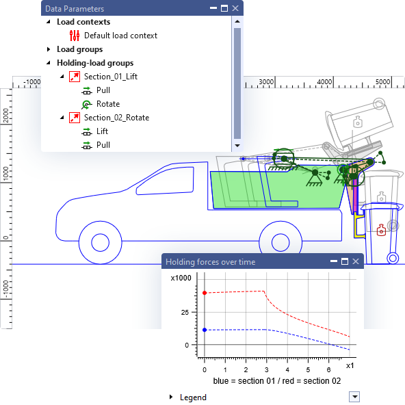
Manage scenarios for force calculations with ease and convenience
ASOM offers various tools for creating and managing load scenarios. Use e.g. the conveniently editable load groups to manage optional loads or load scenarios in general (sets of loads to be used). Use the load contexts for displays to create graphs for different environmental conditions (e.g. simulation direction, temperature, inclination and consideration of defined friction elements).
Additionally, all drives always also contain matching holding load properties within themselves to make the definition of your load systems even simpler and less susceptible to modeling errors.
All kinematic building blocks, at any time, at the push of a button
Use the full range of 2D kinematics for your simulation: gear pairs, belt drives, rack-and-pinion pairings, curved rails / contours, conditions for rolling connections of any two contours (travel connection) and more. You can use all these components, or rather kinematic constraints, in ASOM and simulate resulting linkages of any complexity with any degree of freedom.
Even contour contacts such as those on cams or passively connected hydraulic cylinders can be integrated into linkages in this way.
Model your system exactly as you need it
Kinematic elements can often represent various real elements. For example, rails in ASOM can represent not only rails, but also slots or contours.
Both straight and curved rails (spline rails) can have any number of sliders added to them and can also easily be directly connected to each other via sliders. In combination with suitable parametric constraints, any type of contour-on-contour contacts can therefore be easily modeled. Curved rails are represented by splines and can be edited using either interpolation points or control points.
1.
Get in contact
Request an online presentation of ASOM – completely without obligation.
2.
Net meeting
In an online meeting, we demonstrate ASOM to you and answer your questions.
3.
Evaluate
If you order our basic training course, you can then try out ASOM for three months.
4.
Purchase license
After the evaluation phase, you decide whether you want to purchase a license or not.
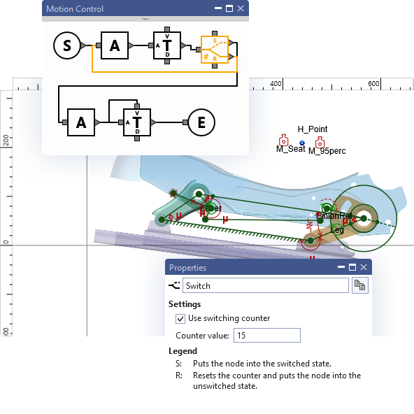
Elegantly create complex motion sequences with the extended drive control
In order to be able to simulate your kinematic system, you must of course impose a desired motion on it (exception: static systems). This, however, does not have to be completely known in advance, but can also adaptive, based on the circumstances of the modeled system that are not known in advance, as drives can be activated or deactivated (or their behavior can change) based on conditions.
The extended drive control with graphical programming in ASOM makes especially easy to define partial movements asynchronously and to synchronize them only optionally. Loops and alternative motion sequences for the same linkage are also possible.
With your know-how, ASOM can become even more effective
If the options we provide for displaying simulation data are not sufficient for you, you can in many cases add the required functionality yourself. With our scripting system, which has access to all simulation data, you often don't have to wait for us to add new functionality for you.
Define new graph types yourself or use script-based expressions to evaluate complex quality criteria for your system. The behavior of many load elements can also alternatively be scripted, if necessary. Thus, you are not limited by the building blocks we currently offer.
A user interface that facilitates working efficiently, alone or in teams
The user interface of ASOM is very easily customizable to meet the needs of different users. This includes, besides the flexible and customizable window arrangement, the availability of themes (light/default/dark) and project settings that allow full user control e.g. over all colors on the canvas.
Together with the built-in template system, this allows users to create and maintain fully customized UI variations for different users or even whole teams/user groups. The project settings also contain all simulation parameters that can be influenced by the user.
Stay well oriented – in the interface and in your model
The element tree of ASOM is organized as a folder hierarchy to bring it closer to the UI concepts of typical CAD programs. New elements can be sorted into specific folders either manually, or automatically, based on their type. Information on element relationships can optionally be displayed in an additional window (sub-elements, connected elements, dependent elements).
In the central simulation log, you will find information not only on events in the drive control, but also in the entire simulation, such as the exact reason why a simulation was terminated or where or in what scripts errors occurred.
ASOM is exactly what you have been looking for? We look forward to hearing from you.
Just contact us, without any obligation, so that we can get to know each other and discuss details at an initial net meeting. We will also be happy to address your individual requirements and to resolve any open questions.