
 1:25
Four-bar linkage with manual force
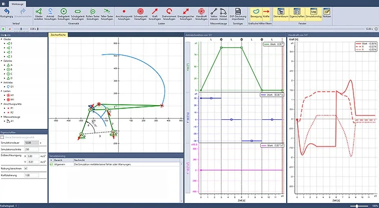
The manual force element shows in real time how the required manual force changes when you move the application point, a bearing or the center of gravity.
From a blank sheet to a finished model: the video shows step by step how to build and analyze a four-bar linkage in ASOMmini.
 3:35
A four-bar linkage is built as a kinematic chain of links and joints. Then the motion, velocities and forces are to be made visible – with a mass on the coupler and friction in the bearings. Finally, the linkage is modified to make it fully rotating.
You build the four-bar linkage in one go and immediately see how it moves and which forces act in the bearings.
A few steps take you from a blank sheet to your first model. More on modeling and motion
Calculated with mass and friction, the bearing forces provide a basis for bearing design. More on force calculation
You see immediately whether the crank rotates fully – and modify the linkage until it works.
1:25
The manual force element shows in real time how the required manual force changes when you move the application point, a bearing or the center of gravity.
 1:56
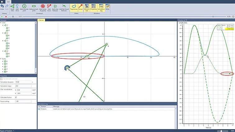
A Chebyshev four-bar linkage guides a point along an almost straight line: with a coupler length of 20 cm, the straight section lies within a corridor of about 1 mm.
 2:29
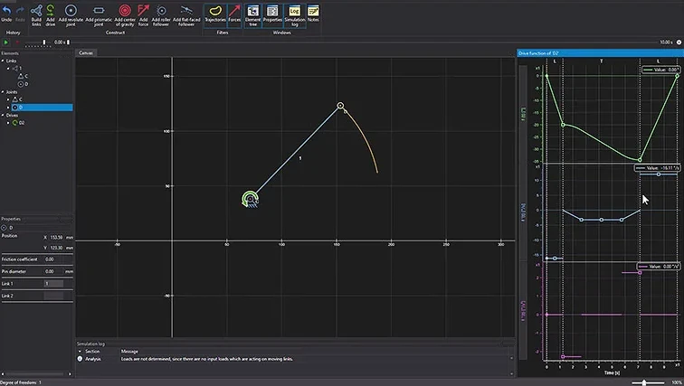
A rotating motion becomes an oscillating motion. You shape the motion profile directly in the diagram, segment by segment.
Describe your mechanism to us. In an online demo, we will show you ASOMmini using your example.