
 3:43
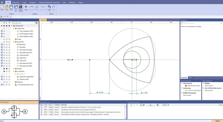
Wankel engine
Constraints fix the gear ratio at 2 : 3. The trajectories of the rotor apexes form the housing contour – even when you change the rotor shape.
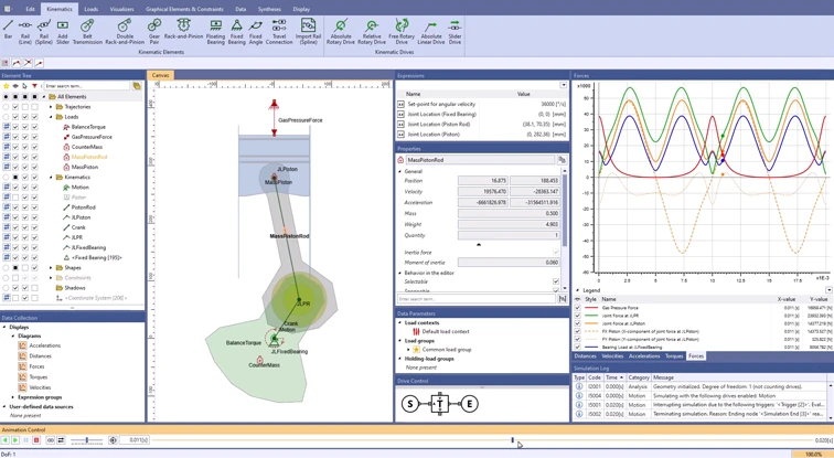
The slider-crank of a two-stroke engine at 6,000 rpm: ASOM calculates the joint and bearing forces, taking the inertia of the moving parts into account.
 1:32
Crank, connecting rod and piston form a slider-crank, with a counterweight on the crank. The forces in the joints and bearings are to be determined. At high speeds and accelerations, inertia is often no longer negligible.
You see early on how strongly inertia changes the forces in joints and bearings, and you factor it into your concept right away.
With inertia taken into account, you design bearings and pins for the forces that occur in operation. More on force calculation
The diagrams show at which crank position the forces peak. More on diagrams
The animation runs in slow motion, while the calculation uses the full speed. This lets you follow even fast motion sequences at your own pace.
3:43
Constraints fix the gear ratio at 2 : 3. The trajectories of the rotor apexes form the housing contour – even when you change the rotor shape.
 1:15
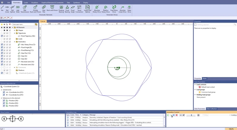
Rotors with three to six apexes compared, each with the matching gear ratio. ASOM shows the matching housing contour for each shape.
 3:05
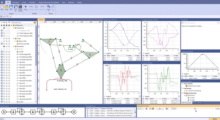
A parallel mechanism with two degrees of freedom: you specify the trajectory, and ASOM provides the angle, speed and torque of the drives, including inertia effects.
Tell us about your mechanism. In an online demo, we will show you ASOM using your own example.