In this video series, we will show you the most common variants of the planar four-bar linkage, as well as their characteristics and special features. These variants can be derived from the theorem of Grashof.
Grashof’s condition for four-bar linkages states: The shortest link of a four-bar linkage can fully rotate in relation to its neighbouring links, if the sum of the lengths of the shortest and longest link is smaller – or at least equal, in the limit case – than the sum of the other two link lengths. The longest link in the four-bar linkage can be a neighbouring link of the shortest link or it can be situated opposite to it.
According to the usual conventions for four-bar linkages, we name the links and joints as follows: The shortest link is always designated a, the remaining links are designated b, c and d in a clockwise direction.
For joints, the following applies, analogously: Joint 1 is between a and d and from there the further numbering up to 4 is also done clockwise.
Alternatively, the fixed link is usually referred to as the frame and the link opposite from it as the coupler. The other two links are often called grounded links.
By deciding which of the links b, c and d is the longest, as well as by different choices for the frame, different types of four-bar linkages can then be derived.
Let us now look at the limit cases of Grashof’s inequality mentioned above. These are the cases in which there are at least two shortest and at least two longest links, from which it follows that the sum of the shortest link and the longest link must now be exactly equal to the sum of the remaining links. Thus, the inequality becomes an equation.
For the arrangement of the pairs of links the following choices are available:
- pairs of links with equal lengths are opposite to each other (parallelogram).
- pairs of links with the same lengths are next to each other (deltoid).
- all 4 links are of the same length (square/rhombus).
In all of these cases (except for the second one), regardless of the frame selection, both of the grounded links are always cranks, similar to the double-crank.
However, in the motion of all of these limit cases, there are always two additional positions where the linkage degenerates and is no longer uniquely constrained. This means that at one point in time all of the links lie on top of each other (or in a line), resulting in multiple possibilities for continuing the motion out of such a situation. This can lead to major problems in practice, especially when starting from such a position. For this reason, such linkages are usually only used in their “safe” ranges, where they do not degenerate.
In the last part of our series we need to look at the last two of these cases.
Let us focus first on the second case, in which links of equal length are always directly adjacent. Here, we can also derive two sub-cases, namely by deciding whether one of the short or one of the long links is chosen as frame.
By choosing a short link as a frame, as shown in the first video, the two neighbouring links can be made to rotate fully relative to the frame. The linkage is then called an isosceles double-crank.
Here, the lengths a to d were chosen as follows:
a and d = 50 (min), b and c = 146 (max)
Thus, the equation applies: a+b = 196 = c+d or a+c = 196 = b+d
If, on the other hand, you choose a long link as the frame, as shown in the second video, you get the isosceles crank-rocker. Similar to the simple crank-rocker, the short grounded link becomes a crank and the long grounded link becomes a rocker.
Here, the lengths a to d were chosen as follows:
a and b = 100 (min), c and d = 158 (max)
Thus, the equation applies: a+c = 258 = b+d or a+d = 258 = b+c
Both linkages are only used in special cases, because, unlike their respective namesakes, they can cause problems due to the possibility for degeneration.
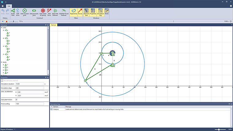
The third case, sometimes also called a rhombic or rhombus-crank, represents in itself a special case to the first two cases, since here not only two links are of the same length, respectively, but all four. This means, that when the linkage degenerates, not only do the links lie on top of each other, but the joints lie on top of each other in pairs as well.
If you simulate such a system, as shown in the third video, you should be aware that in practice even slight deviations in the production of the components (which can hardly be avoided) may result in a significantly different behaviour, both in the motion and in the distribution of forces.
Here, the lengths a to d were chosen as follows:
a, b, c and d = 150 (min and max)
Thus, the equation applies: a+b = 300 = c+d or a+c = 300 = b+d or a+d = 300 = b+c
In ASOMmini, such linkages can be designed, simulated and analyzed kinematically very quickly and easily. They can also be modified and optimized in real time. The same also applies for more complex kinematic systems, which can also be implemented without difficulty using our software.