
In this video series, we will show you the most common variants of the planar four-bar linkage, as well as their characteristics and special features. These variants can be derived from the theorem of Grashof.
Grashof’s condition for four-bar linkages states: The shortest link of a four-bar linkage can fully rotate in relation to its neighbouring links, if the sum of the lengths of the shortest and longest link is smaller – or at least equal, in the limit case – than the sum of the other two link lengths. The longest link in the four-bar linkage can be a neighbouring link of the shortest link or it can be situated opposite to it.
According to the usual conventions for four-bar linkages, we name the links and joints as follows: The shortest link is always designated a, the remaining links are designated b, c and d in a clockwise direction.
For joints, the following applies, analogously: Joint 1 is between a and d and from there the further numbering up to 4 is also done clockwise.
Alternatively, the fixed link is usually referred to as the frame and the link opposite from it as the coupler. The other two links are often called grounded links.
By deciding which of the links b, c and d is the longest, as well as by different choices for the frame, different types of four-bar linkages can then be derived.
Let us now look at the limit cases of Grashof’s inequality mentioned above. These are the cases in which there are at least two shortest and at least two longest links, from which it follows that the sum of the shortest link and the longest link must now be exactly equal to the sum of the remaining links. Thus, the inequality becomes an equation.
For the arrangement of the pairs of links the following choices are available:
- pairs of links with equal lengths are opposite to each other (parallelogram).
- pairs of links with the same lengths are next to each other (deltoid).
- all 4 links are of the same length (square/rhombus).
In all of these cases (except for the second one), regardless of the frame selection, both of the grounded links are always cranks, similar to the double-crank.
However, in the motion of all of these limit cases, there are always two additional positions where the linkage degenerates and is no longer uniquely constrained. This means that at one point in time all of the links lie on top of each other (or in a line), resulting in multiple possibilities for continuing the motion out of such a situation. This can lead to major problems in practice, especially when starting from such a position. For this reason, such linkages are usually only used in their “safe” ranges, where they do not degenerate.
In this fourth part of our series we will look at the first of these cases, where links of equal length are opposite each other. This case can be divided into two sub-cases. If we arrange the links as a parallelogram without any of them crossing each other, we get a parallel-crank (also called a parallelogram guide). Throughout its entire motion, its two cranks are always parallel to each other. They also have a constant angular velocity. These properties make the parallel crank a frequently used component, e.g. as a windscreen wiper, as a double arm of a desk lamp, or as part of a drawing machine.
Here, the lengths a to d were chosen as follows:
a and c = 32 (min), b and d = 50 (max)
Thus, the equation applies: a+b = 82 = c+d or a+d = 82 = b+c
If, on the other hand, you allow the longer links to cross (similar to an hourglass figure), as shown in the second example, you get the antiparallel-crank. It is occasionally used in mechanical switches. The main problems here are the fact that the relative angular speeds can vary widely at some joints, and the fact that the coupler rotates twice relative to the frame for each revolution of the cranks.
Here, the lengths a to d were chosen as follows:
a and c = 100 (min), b and d = 223 (max)
Thus, the equation applies: a+b = 323 = c+d or a+d = 323 = b+c
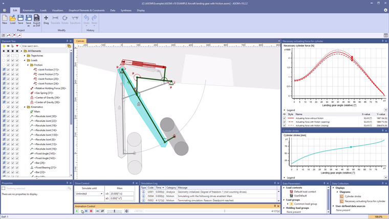
In ASOMmini, such linkages can be designed, simulated and analyzed kinematically very quickly and easily. They can also be modified and optimized in real time. The same also applies for more complex kinematic systems, which can also be implemented without difficulty using our software.