The individual steps for this are as follows:
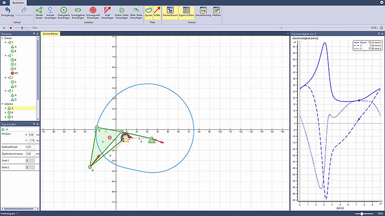
- A four-bar linkage is constructed as a kinematic chain
- The rack-mounted object is defined
- A drive function is defined at one of the four rotary joints
- Tracks showing the kinematic movement are switched on
- A diagram of the velocity over time including its components is created
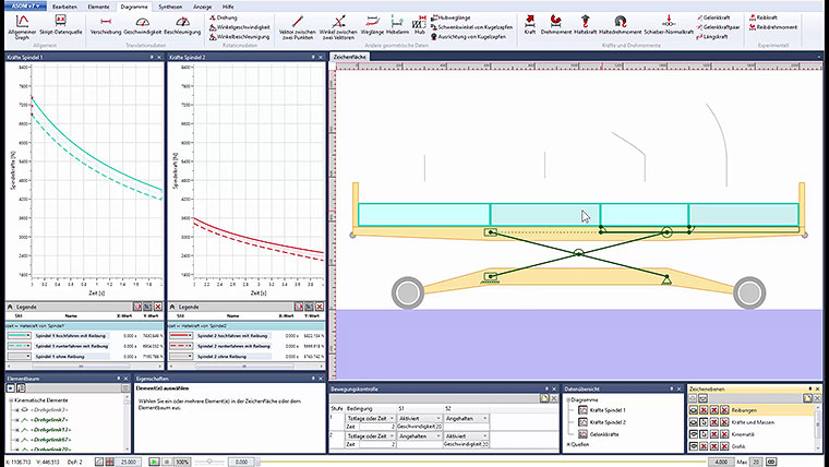
- The coupler is given a mass and the resulting bearing forces are visualized
- Friction is added to the bearing joints
- The coefficients of friction and the pin diameters are partly modified
- The kinematic is adapted until it is able to turn fully
- The animation is started


