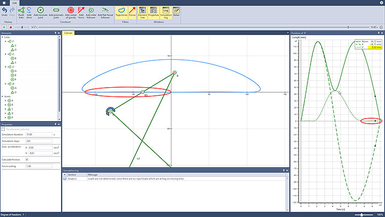
A straight-line mechanism implemented by a linkage (as opposed to a straight guide or bearing) is used to convert a rotary motion into a linear motion. The simplest solutions for this task involve four-bar linkages, as is the case here.
The ratio of the lengths of the links is L1 : L2 : L3 = 4 : 5 : 2, also resulting in the fact that one of the grounded links (L2 and L4) is orthogonal to the frame at each of the two outermost points of the movement.
Since this is only an approximate straight-line mechanism, it makes sense to also look at its accuracy. In the example shown above, for an assumed coupler length of 20cm, the “straight” part of the curve can be enclosed in a corridor with a width of 1mm. The corridor width can be reduced to less than 0.2mm for the same coupler length, as is shown in the second example, if the ratio L1 : L2 : L3 = 5 : 6.5 : 2 is used instead of the original ratio of 4 : 5 : 2. The length of the “straight” part of the curve is reduced by about 11{43744c794202440f614bdd815a49e21f8101affb3f7b8e3743fe0e62bc32706b} at the same time, though.
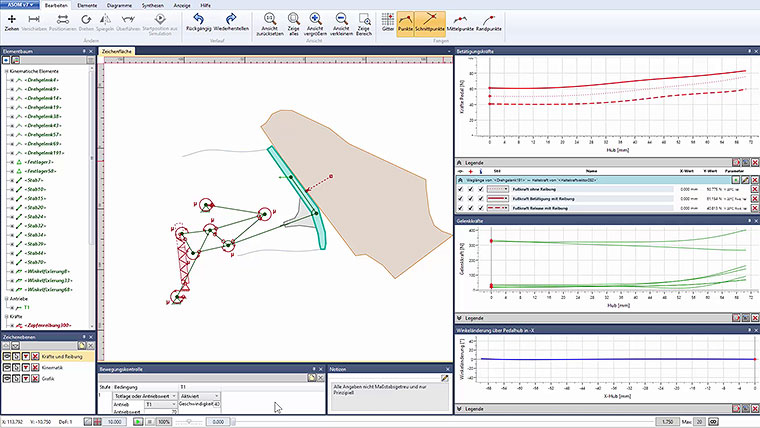
The accuracy of the straight-line mechanism is illustrated by looking at the Y-coordinate of the point P. In addition, the program could also be used to analyze and optimize arising bearing reaction forces and friction.


