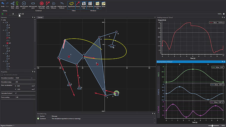
The degree of freedom of the system is ‘1’.
A force is introduced and the resulting bearing forces are displayed graphically in the animation plane. The necessary holding force at the drive location is also determined and output as a diagram.
The friction in the system is taken into account.
Since changes of direction occur for the relative angular velocities at the joints, corresponding steps appear in the graph of the holding force.