Although our six-bar syntheses strictly speaking only allow the specification of 2 plane conditions (plane = point and angle), it is still possible to design six-bar linkages in ASOM v7 to fulfill 3 (or in principle even more) plane conditions.
Instead of using scripts to create only numeric displays in expressions, as shown in our last example video, you can also use scripts to create graphical displays in diagrams.
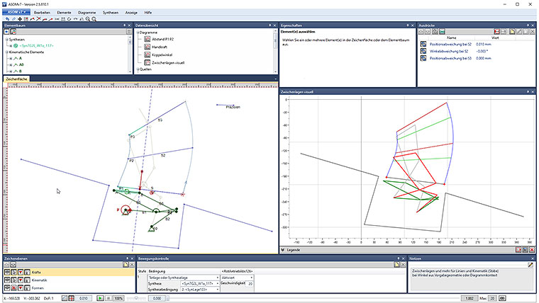
In this example, we therefore used scripts to recreate a relevant part of the canvas in a diagram and to extend it with additional display elements. For this purpose, the bars of the kinematic system as well as the graphical elements representing the plane specifications, the moving plane, and the mounting zone are reproduced in the diagram.
It is shown visually how close the trajectories of the end points of the moving plane come to the middle plane specification. It is also shown where the moving plane is, just when it has exactly the angle of the middle plane specification. In addition to displaying the kinematics at the beginning (green) and end (grey) of the simulation, an intermediate state is also displayed in red at just this point in time (coupler angle = angle of middle plane specification). In light green, two intermediate states of the moving plane are displayed at certain given angles (here: 10° and 30°). Finally, the ending plane is only drawn in red if the moving plane actually reaches it exactly.
With this additional information, which is always available in real time, the design parameters of the system can now be influenced in a purposeful manner and an insight into whether solutions exist and where they are located can be quickly obtained. As is well known, the solution space shrinks with every additional design constraint, so that with this approach (middle constraint does not need to be fulfilled exactly) an acceptable approximation can often be found even for problems that do not have an exact solution.
Another advantage of this “mirroring” of elements from the canvas into a diagram is that you can zoom in to different regions on the canvas and in the diagram to, e.g., observe small but distant effects of small changes.
The forces in this example are only meant to illustrate the fact that force considerations of arbitrary complexity can be considered at the same time as the kinematic design (e.g. as further secondary constraints for the design). In the form as shown, they do not necessarily represent the real force situation at a rear spoiler.


